edit: This post has been updated as of 6/13/2012, to account for a previous missed step in the shading network (insert clamp node).
 |
| Example shader |
This is a really great technique for quickly generating some chips and dents along the outside edges of your model, as well as adding a layer of dirt (in
part 2) to the more recessed areas. Once you have a handle on this technique you can then customise and apply it to all manner of materials. For this shader we will be utilising two of the Mental Ray nodes- a
'mib_amb_occlusion' node as well as a
'mia_roundcorners' node.
Firstly, let's work on generating some chips and dents for our model...
To get a better sense of what we're aiming for, here are some images which show the effect of edge chipping...
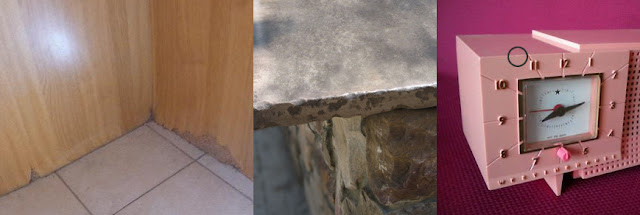 |
| Examples of images of edge chipping on a variety of materials |
Alright. Some nice subtle and not so subtle edge chipping. By looking at these shots we can appreciate that many objects in the real world show signs of this kind of wear and tear. What this means when it comes to our models and textures is that often times it is not enough to just simply apply a bevel to our object- but we should also think about introducing some variation into the bevel itself for added realism. We want to break up the bevel. How much will depend on our object, it's age and the material we are trying to represent.
So let's start... In the hypershade, bring two new 'mia_roundcorners' nodes into the work area. We also need to bring in an additional node- one of the Maya utility nodes- called 'Vector Product'.
Double click on the Vector Product node to bring up it's attributes window. Then, with mouse pointer over one of the roundcorners nodes in the hypershade, middle click and drag over to the 'input 1' slot in the Vector Product attributes. Release the middle button and the two nodes should now be connected. Do the same for the other roundcorners node but this time connect it to the 'input 2' of the vector product.
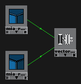 |
| Two roundcorners_bump nodes connected to input 1 and input 2 of a Vector Product node |
So far, so good.
The next step is to change the radius value in
one of the roundcorners nodes. Before doing that though, for testing purposes let's also bring in a Maya surface shader to the work area in the hypershade. This will act as our 'dummy' shader. Double click on the surface shader to bring up its attributes, then middle mouse drag from the Vector Product node into the 'color' slot of the surface shader. Now we have the output from the Vector Product node running into the colour slot of the surface shader. Create a standard poly cube and apply the surface shader to the cube. A render (we will need to be rendering in Mental Ray) will show that our cube is black.
Go into each of the roundcorners nodes and change the 'bump mode' parameter there from 0 to 5. Make another render. Our cube should now be white.
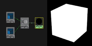 |
A surface shader is applied to our test object (bump mode set to 5 in our roundcorners nodes)
|
Now, in the attribute settings of
one of our nodes, increase the radius to .1. Hit render. You should get back a result that now looks something like this...
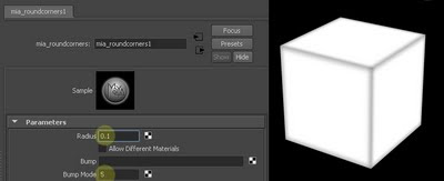 |
| Adjusting the radius in one of the roundcorners nodes |
Your result may differ depending on how big your cube is, so you may want to adjust the radius up or down. This is why it's a good idea to use a dummy shader as it helps you to see exactly what you're doing. For even faster feedback, you can use Mental Ray's IPR rendering while you make your adjustments.
Now we have a great starting point for our chips and dents. This will act as our basic mask and tell our shader where and where not to apply wear and tear.
Create a new ramp and then alter the gradient colours to match the below image, with black (or any colour) on bottom and white on top.
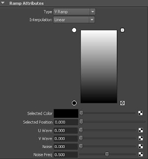 |
| Adjusting the ramp |
The next step requires us to insert a Clamp node between the Vector Product Node and the Ramp. If we don't clamp the output of the vector product then we'll end up with some funky results. Create a Clamp node and middle click drag the Vector Product onto the Clamp and choose 'input'. We'll need to clamp the new minimum values to 0 and new maximum values to 1. The attributes in the Clamp node should look like this...
 |
| You will need to clamp the output from the Vector Product |
The next step requires using the connection editor. Middle click and drag from the Clamp node onto the ramp, then select 'Other...' from the pop up menu. Once inside the Connection Editor, look for the parameter 'output' on the left hand side window (the vector product node). Click the + sign to the left of 'output' and then click on either outputX,Y, or Z. On the right hand side panel (the ramp) look for 'uvCoord', it should be greyed out. Click the + sign next to it and then select 'vCoord'.
 |
| Parameters in italics are connected |
Now that that's taken care of, we'll create a procedural texture in order to break up the edges. Here I am using a 2D mountain node but you can use whatever you like. For a more chipped effect it makes sense to use a texture with a hard falloff. Here are the settings I've used in my mountain texture.
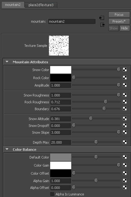 |
| Mountain settings |
Click on the ramp again, make sure the black colour in your gradient is selected, then middle click and drag your new texture to the 'selected color' slot of your ramp. Your network should now look something like this...
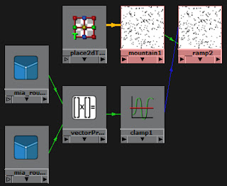 |
| The shading network so far, dummy shader removed |
Bring in a new
'mia_material x' node as well a
'bump 2D' or
'bump 3D' node (depending on whether your texture is a 2D or 3D texture). Middle drag the ramp to the 'Bump Value' slot of your bump node. Then connect the bump to the 'Overall Bump' slot of your mia_material. Assign the mia_material to your test object and do a quick render.
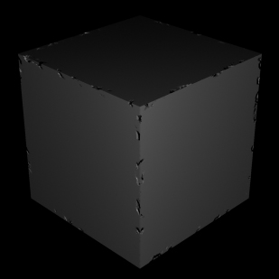 |
| The basic chipping effect |
Alright. We now have some basic chips on the edges of the object. The effect looks a little extreme but we can tone down the intensity of the bump in a few ways- by adjusting the 'bump depth' in the bump node, by adjusting the texture (in my case I might alter the 'rock color' in my mountain texture from black to a light grey), and/or by changing the radius in our roundcorners node.
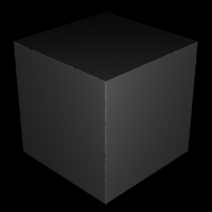 |
| Adjusted for subtlety |
A couple of things before wrapping up. The first is to mention that this technique works very well on hard edged objects, but fails on pre-bevelled or smooth objects. Basically, it will work where roundcorners works on your object (great for mid-distance objects with simple geometry). The second thing is that you can enhance the look of your shader by putting
another roundcorners node into the 'Standard Bump' slot of your mia_material_x (you need to use mia_material_x as the standard mia_material (the non x variety) does not have two slots for bump). Just adjust the radius on your new roundcorners to get an all round bevelling effect on your object. The chips and dents will interact well with the new bevel as the standard bump gets applied on top of the overall bump. If your bumps are reversed then you will not get that nice broken line in the lighting of your bevel, which is really the whole point of this technique.
That's it for part 1. Stay tuned for
Part 2!
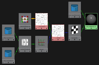 |
| Final shader |
PS - Many thanks go to J M Bihorel who originally showed me the basis for this very handy technique. You can find J M at his blog,
here...
edit: This post has been updated as of 6/13/2012 to account for a previous missed step in the shading network (insert clamp node).


This comment has been removed by the author.
ReplyDelete